
The one thing I truly dreaded when thinking about beginning this swap was the terrible rainbow spaghetti, aka, the wiring harness. I was a bit out of my depth but knew it was a challenge I had to tackle. The first step was to purchase the whopping $40 1 month subscription to alldata.com (not sponsored) for the C5 Corvette. The C5’s were incredibly futuristic in the sense that every little component was controlled by a separate module, meaning there were lots of wires in the harness that I did not need. Time to rip this thing apart
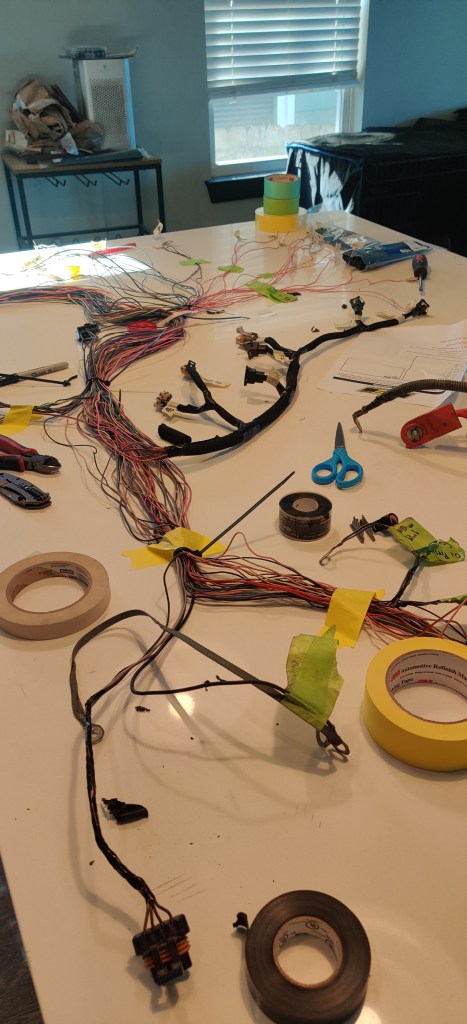
After [carefully] ripping off the factory loom, I was left with a myriad of connectors and wires and absolutely no idea what each did. The smart thing to do in hindsight would be to label everything while the connectors were still on the car but hey I’m not perfect. Sucks but I wasn’t too worried.
I probably should have been worried but I knew ahead of time that I was going to have to remove, swap, and add all kinds of pins to the PCM connector. This means I would have to trace every single wire down to the PCM, thus revealing its intended function and solvingwhat the heck these connector functions were.
The PCM that came from the engine is an 896 series. I do feel special because these are considered kinda rare to find, but functionally they are the same as the 411 PCMs. Whatever, I’m still like the unique factor. Both support drive-by-wire (DBW) and drive-by-cable (DBC) throttles. The LS1 I bought is DBW…so naturally I said f that and wanted to go DBC. Why? Sure, DBW gives you better tunability and very immediate throttle response (this is a debate but electrons travel faster than mechanical action so whatever). BUT there is just something so cool about thwapping the throttle flap and revving the engine from under the hood. Yup that’s the only reason why. I just wanted to rev from under the hood to look cool. So to support this cool factor, I had to add a whole new throttle position sensor (TPS) and idle air control (IAC) sensor. Worth it? I mean its just a matter buying a pintail connector, soldering on your own wire and measure the length to the PCM. Easy peasy.
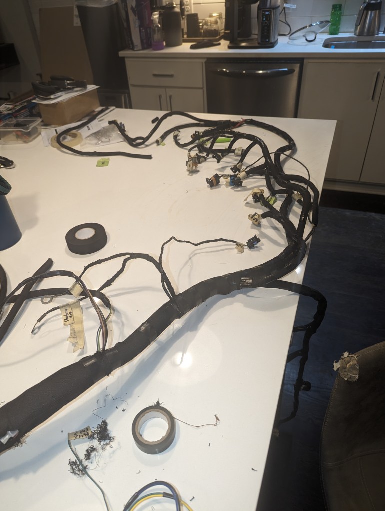
I did have to remove a ton of connectors that controlled suspension, ABS, and other weird modules. That sucked and it left me with a ton of extra 20+ yr old wire. I’m sure it’ll come in handy at some point so I kept it.
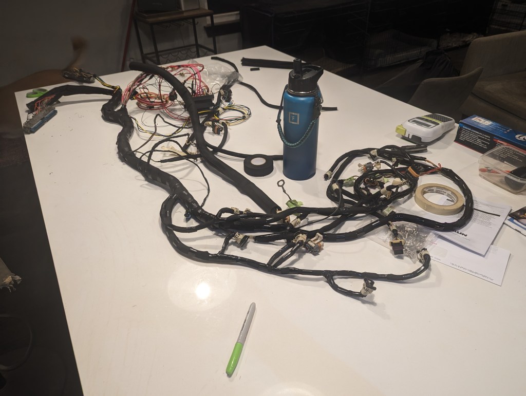
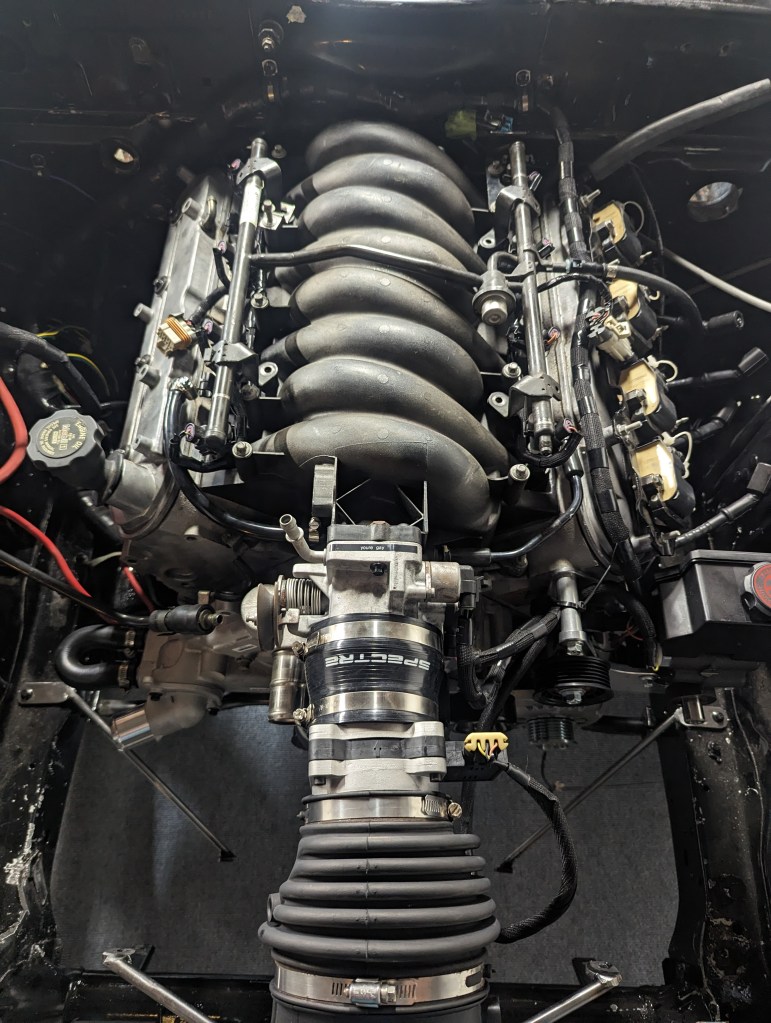
Once I was pleased with the PCM connector pinouts, I brought the harness over to the engine bay and began measuring the lengths needed for each connector to its respective sensor. This is a very tedious yet valuable process. You definitely don’t want to loom the harness outside the car only to realize some things just don’t fit the way they did. I may or may not have learned that the hard way.
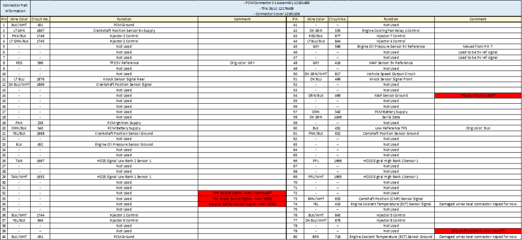
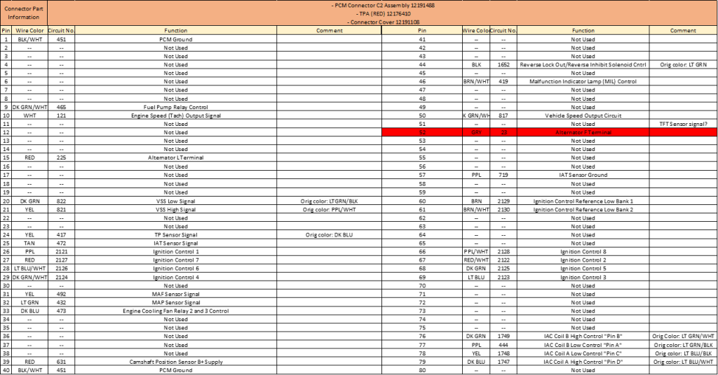
The table down here is the final pinout for the PCM. It’s basically the same as a 2000 F-body with a few extra stuffs taking advantage of the extra 5V and low reference signals coming from the computer. Gotta use what you got ya know??
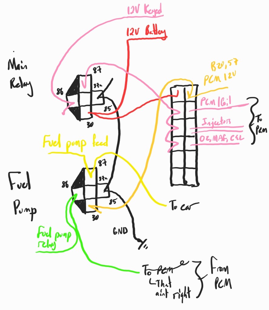
I wired main fuse box and relays using the write-up guide from UCanDoIt2’s Project Rowdy on YouTube.
These two sheets were a godsend when trying to figure out how to power the PCM and engine components. The main relay is wired in a very basic fashion. If you don’t know what a relay is, its essentially a switch, like how you turn a light on and off. But instead of your hand doing the on/off state, a signal from the PCM controls that. Let’s start simple, Pin 85 on the relay is wired to ground and Pin 30 is receiving a constant 12V. These form the basic power supply for the relay’s switching action. The trigger or switch on the relay is Pin 86, and is wired to the keyed ignition 12V at the ignition switch. So when the key is turned to the “On” position, Pin 86 will receive voltage causing the relay switch to activate. This will swing a mechanical arm (youcan hear an audible click when this happens) to open the circuit between Pin 30 and Pin 87. Pin 87 will then power a bank of fuses, which then turn on the PCM and components. Similarly, the fuel pump relay still has the ground and 12V at Pins 85 and 30. Except now, once the PCM is turned on, the fuel pump signal wire is triggered to send the “on” signal to the fuel pump.
This was a fun adventure, wiring harnesses really aren’t all that scary. Once you understand it, you can wow people with your vast knowledge of pinning and de-pinning wires and tracing them to connectors. Its not rocket science but its probably some type of science.
I should talk about HPTuners at some point. I guess I’ll do that in the next post.

Leave a comment